CETC Tier-1 distributor Jarwey|SiC MOSFET vs CoolMOS SJ replacement
For years, PFC stages, flyback/forward adapters, HV DC-DC converters, and mid-power inverters defaulted to silicon superjunction MOSFETs (CoolMOS™-class SJ). As SiC MOSFETs mature and scale, device pricing keeps falling—often approaching or even undercutting comparable SJ parts in mid-power bins—while switching loss, Qrr, and high-temperature behavior remain clearly better. SiC is no longer only a “premium upgrade”; it is becoming a practical direct replacement / second-source path for silicon SJ.
Jarwey is a Tier-1 distributor of SiC power devices from CETC Guiji Nanfang (CETC 55 Institute), a subordinate unit of China Electronics Technology Group (CETC)—selection support, datasheets, sampling & small batch, lead-time coordination.
Jarwey (CETC SiC Tier-1 distributor) supplies CETC / 55th Institute G3 devices such as WM3HA300065E and WM3HA330090E with explicit 15 V / 0 V gate drive compatibility: no negative turn-off rail required, closer to common SJ and flyback-controller habits, so you can evaluate a silicon→SiC swap without rebuilding the whole gate-drive board.
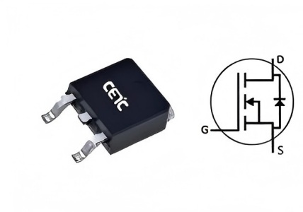
Figure: G3 SiC MOSFET (TO-252, 15 V / 0 V capable)
Why “SiC replaces SJ” is timely now
Historically, three blockers slowed adoption more than raw performance:
- Device ASP well above CoolMOS™-class SJ
- Gate-drive complexity (many SiC parts expect negative turn-off)
- Validation cost around layout, Miller turn-on, and body-diode behavior
That picture has changed: process maturity drives cost down; SMPS/PFC-oriented G3 parts document +15 V turn-on / 0 V turn-off; lower Qrr and switching loss unlock higher frequency or smaller magnetics and heatsinks. On a system BOM basis, many designs already pencil out—sometimes cheaper overall than staying on silicon SJ.
SiC MOSFET vs silicon SJ / CoolMOS™ (selection table)
| Dimension | Silicon SJ / CoolMOS™ | SiC MOSFET (G3 15 V / 0 V class) |
|---|---|---|
| Switching loss / frequency headroom | Proven mid-frequency workhorse | Lower switching loss; easier to raise fSW and shrink magnetics |
| Qrr / hard-commutation friendliness | Large body-diode Qrr limits hard recovery | Much lower Qrr; friendlier bridge / hard-switch use |
| Gate drive | Typically ~10–15 V on, 0 V off | 15 V / 0 V compatible with many flyback controllers; can drop negative bias supply |
| Thermal / power density | Mature, but cooling/size often dominate | Stronger high-temp behavior → higher power density |
| Device cost trend | Established pricing | Falling fast; some bins near / below SJ ASP |
| System cost | Cheap FET, larger magnetics/heatsink possible | FET + drive + magnetics + cooling often wins the TCO comparison |
Parts to evaluate (Jarwey)
| Part | VDS | RDS(on) typ. | Package / drive |
|---|---|---|---|
| WM3HA300065E | 650 V | ~300 mΩ @15 V; ~250 mΩ @18 V | TO-252-2L; 15 V / 0 V flyback-friendly |
| WM3HA330090E | 900 V | ~330 mΩ @15 V; ~250 mΩ @18 V | TO-252-2L; 15 V / 0 V for higher-bus adapters |
Specs per latest datasheet. Shared pitch: SiC performance + SJ-like drive simplicity + cost-effective alternate sourcing.
7-step replacement checklist
- Voltage class: is the incumbent SJ 600–650 V or 800–900 V?
- RDS(on) at temperature: compare at operating Tj, not only 25°C brochure numbers.
- Gate drive: can the existing driver deliver ~15 V (or 18 V) on and 0 V off?
- Topology: boost PFC / flyback vs half-bridge? Hard body-diode recovery?
- Layout / Miller: with 0 V turn-off, review RGoff and loop inductance on high-dv/dt bridges.
- Body-diode Vf: SiC Vf is typically higher than silicon—confirm freewheel paths.
- System BOM: price the FET + bias supply + magnetics + heatsink before calling the swap “too expensive.”
Why Jarwey (flexible, cost-controlled path)
- Mainstream SJ application coverage without import-brand premium
- Verifiable G3 SiC specs (RoHS / datasheet parameters)
- 15 V / 0 V drive cuts redesign cost; sampling and small-batch delivery stay flexible
- Fit for PSU OEMs, inverter teams, and EMS second-source / efficiency pilots
Resources
WM3HA300065E (650 V) product page & datasheet
WM3HA330090E (900 V) product page & datasheet
Jarwey product center · SiC MOSFET
Inquiry: kerry.w@jarwey.cn
Summary
When SiC hits the trifecta of switching performance, simple 15 V / 0 V drive, and competitive cost, direct replacement of silicon SJ / CoolMOS™ stops being a lab exercise. Start from your silicon design’s voltage, drive, and loss budget; sample WM3HA300065E / WM3HA330090E; judge efficiency, temperature rise, then full system BOM. For many mid-power PSU programs, the replacement window is already open—especially for India/EM cost-sensitive builds and Europe RoHS-driven efficiency upgrades.
Note: selection guide only—not a pin/parameter swap guarantee. Validate against measured waveforms and the latest datasheet before release.
Jarwey · CETC SiC Tier-1 distributor · kerry.w@jarwey.cn · Contact.
Related Articles