CETC Tier-1 distributor Jarwey|1200V SiC MOSFET WM2HA020120L inverter checklist
In string PV inverters, storage PCS, and industrial VFDs / inverters, the DC bus often sits in the 800–1000 V+ range. A 650 V class is no longer enough, so engineers enter the 1200 V SiC MOSFET pool and must check voltage margin, RDS(on), current / paralleling, gate drive, and thermals—not the “replace CoolMOS in a flyback” playbook.
Jarwey is a Tier-1 distributor of SiC power devices from CETC Guiji Nanfang (CETC 55 Institute), a subordinate unit of China Electronics Technology Group (CETC)—selection support, datasheets, sampling & small batch, lead-time coordination.
CETC / CAS Institute 55 G2 part WM2HA020120L targets this tier: product page lists VDS=1200 V, RDS(on)=20 mΩ, ID@25°C=100 A, with fast switching, low capacitance, and paralleling-friendly narrative. Use the datasheet PDF on the product page; qualify on the bench before production.
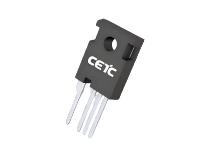
Figure: WM2HA020120L (1200 V / 20 mΩ class)
How this differs from our 650 V / SJ articles
- Prior guides focus on 650 V SiC as a silicon superjunction / CoolMOS alternate plus cost · drive · lead-time gates—mostly SMPS / PFC / flyback.
- This piece only answers: how to evaluate WM2HA020120L in the 1200 V PV / industrial inverter pool. It does not reprint CoolMOS tables.
Metric snapshot
| Item | WM2HA020120L (product page) | How to use it in inverter eval |
|---|---|---|
| VDS | 1200 V | Map to max bus + surge / inductive spikes |
| RDS(on) | 20 mΩ (headline) | Use hot RDS(on) curves—not 25°C only |
| ID@25°C | 100 A | Check continuous / peak and derating at temperature |
| Tech angle | G2; fast, low C, parallel-friendly | Good for paralleled legs / higher fsw; still verify sharing & Miller |
8-step PV / industrial inverter checklist
- Bus & voltage margin: Max DC bus in normal/fault plus switching spikes—still inside a 1200 V safe zone? Snubber / layout as needed.
- Topology role: Hard- vs soft-switched duty in full-bridge / half-bridge / 3-level—do not reuse PFC freewheel loss intuition.
- Conduction vs switching split: At target fsw, duty, and Tj, separate 20 mΩ conduction loss from Eon/Eoff (datasheet).
- Paralleling & current share: Symmetric gate loops, source inductance, thermal coupling—“easy to parallel” is not layout-free.
- Gate drive & Miller: Stay in recommended VGS; re-check RG and clamp / negative bias under high dv/dt—not validation-free.
- Thermals & package process: Heatsink, insulator, torque, power cycling; 100 A headline ≠ adequate cabinet airflow.
- EMI / creepage: Common-mode noise after raising fsw; safety creepage and cabinet grounding together.
- Sampling & second source: Pilot against incumbent 1200 V SiC or IGBT module BOM; datasheets, MOQ, and selection support via Jarwey.
Important: Entering an evaluation pool is not pin-to-pin without validation. Final authority is the latest datasheet and board / cabinet measurements.
Why teams evaluate this path
- Aligns with common 1200 V PV / PCS / industrial inverter needs while helping control BOM cost
- Specs are checkable on the product datasheet (voltage, RDS(on), current curves)
- Flexible delivery: sampling, small batch, and lead-time coordination by project; can be paired with 650 V CETC SiC on the same program
- Useful for validation fixtures, channel kits, and pre-module device trials
Datasheet & inquiry
- Product page / PDF: WM2HA020120L
- Related (650 V / SJ angle—do not conflate): CETC SiC cost · drive · lead-time gates · SiC MOSFET ↔ CoolMOS overview
Send your current 1200 V SiC / IGBT PN, topology, bus voltage, fsw, and parallel count to Jarwey for alternate candidates, samples, and lead time: kerry.w@jarwey.cn · Contact
Takeaway
For 1200 V PV / industrial inverter switches, run WM2HA020120L through voltage margin, hot 20 mΩ loss, paralleling, and Miller/drive checks first—then BOM and lead time. Datasheet on the product page; samples, small batch, and selection support: Jarwey.
Jarwey · CETC SiC Tier-1 distributor · kerry.w@jarwey.cn · Contact.
Related Articles